
1.Industrial lens mounts
There are three mainstream lens mount types: F-mount, C-mount, and CS-mount. The F-mount is a universal mount, generally suitable for lenses with a focal length greater than 25mm; while when the focal length of the objective lens is less than 25mm, due to the small size of the objective lens, a C-mount or CS-mount is used, and some also use an M12 mount.
The difference between the C mount and the CS mount:
The difference between C-mount and CS-mount interfaces lies in the distance from the lens-camera contact surface to the lens’s focal plane (the position where the camera’s CCD image sensor is located): this distance is 17.53 mm for C-mount and 12.5 mm for CS-mount.
C-mount lenses are compatible with C-mount cameras, and CS-mount lenses are compatible with CS-mount cameras. A C-mount lens can be used with a CS-mount camera by adding a 5mm C/CS adapter ring. However, a CS-mount lens cannot be used with a C-mount camera.
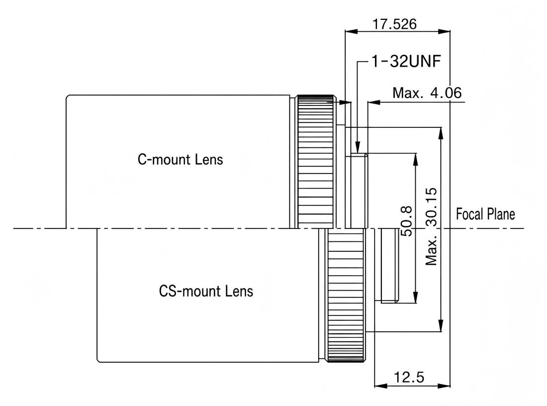
Industrial lens mounts
2.Basic parameters of industrial lenses
1)Field of View (FOV): Refers to the visible area of the object being observed—specifically, the portion of the object that fills the camera’s image sensor. (Field of view is an essential factor to consider when selecting a model.)
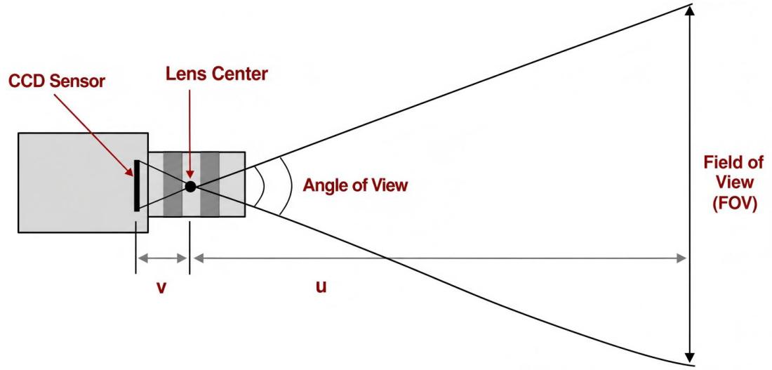
Field of view diagram
2)Working Distance (WD): Refers to the distance from the front of the lens to the object being inspected—specifically, the distance to the surface where a clear image is formed. (Key factors to consider during selection include whether the working distance is adjustable and whether there is sufficient installation space.)
3)Resolution: The size of the smallest resolvable feature on the object under inspection that the imaging system can detect. In most cases, the smaller the field of view, the better the resolution.
4)Depth of Field (DOF): The ability of a lens to maintain the required resolution when an object is positioned closer to or further from the optimal focal point. (It is necessary to determine whether the customer has specific requirements regarding depth of field.)
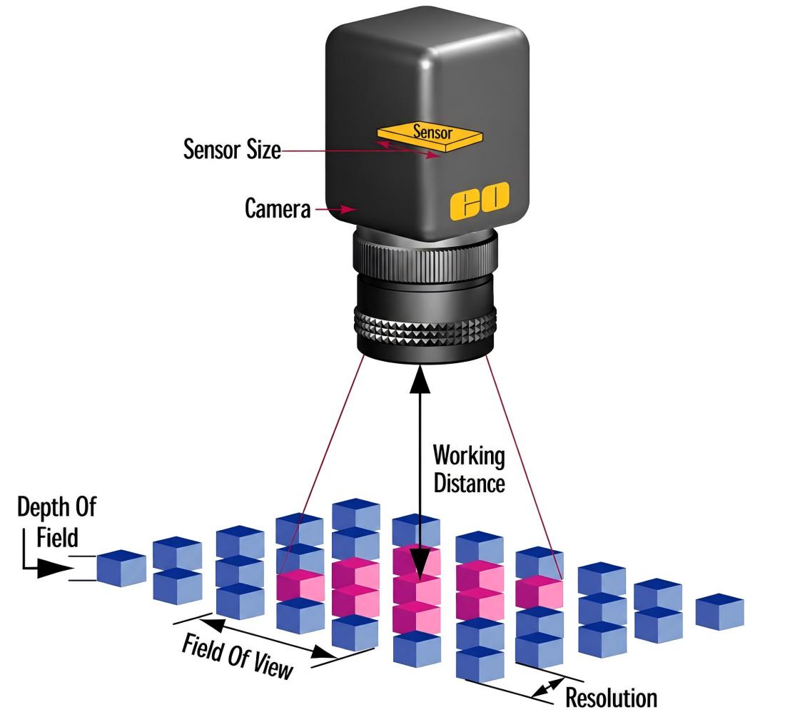
Depth of field diagram
3.Other parameters of industrial lenses
1)Image sensor size: The size of the active area of the camera’s image sensor, typically referring to the horizontal dimension. This parameter is crucial for determining the appropriate lens magnification to achieve the desired field of view. The lens primary magnification (PMAG) is defined by the ratio of the image sensor size to the field of view. Although the image sensor size and field of view are fundamental parameters, PMAG itself is not classified as one.
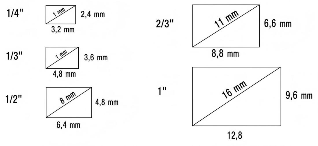
Schematic diagram of photosensitive chip
2)Focal length (f): A measure of light convergence or divergence in an optical system, defined as the distance from the optical center of the lens to the focal point where light converges. In a camera, it refers to the distance from the center of the lens to the imaging plane (such as film or a CCD sensor). (Formula to remember): f = {Working Distance / Long Side (or Short Side) of Field of View} × Long Side (or Short Side) of CCD.
The effects of focal length are as follows: The shorter the focal length, the greater the depth of field; the shorter the focal length, the greater the distortion; and the shorter the focal length, the more severe the vignetting, resulting in reduced illumination at the edges of the image.
3)Resolution: Indicates the minimum separation between two points discernible by a set of objective lenses.
0.61 × Wavelength (λ) / NA = Resolution (μ)
The calculation method above can theoretically determine the resolution, but it does not account for distortion.
※ Wavelength used: 550nm
4)Resolving Power: The number of black and white line pairs visible within a 1 mm span; unit: (lp)/mm.
MTF (Modulation Transfer Function)
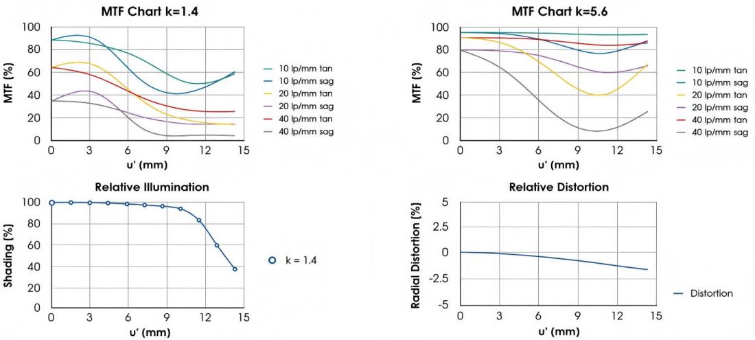
MTF diagram
5)Distortion: One of the metrics used to evaluate lens performance. It refers to an imaging error in an optical system where straight lines lying in the subject plane—but not passing through the optical axis—are rendered as curved lines in the resulting image. Distortion aberrations only affect the geometry of an image, not its sharpness.
6)Aperture and F-number: The aperture is a mechanism—typically located inside the lens—that controls the amount of light entering the lens. Aperture size is expressed using F-numbers, such as F1.4, F2.0, and F2.8.
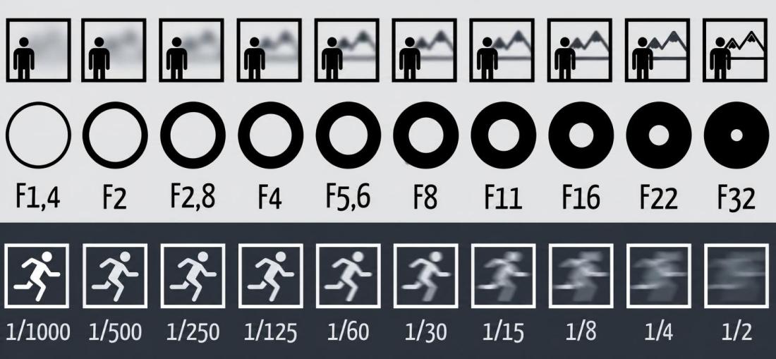
Aperture value diagram
7)Optical magnification: The formula used to calculate the primary magnification is as follows: PMAG = Image sensor size (mm) / Field of view (mm).
8)Display Magnification: Display magnification is widely used in microscopy. The display magnification of the object being viewed depends on three factors: the optical magnification of the lens, the size of the industrial camera’s image sensor (sensor format), and the size of the display monitor.
Display Magnification = Lens Optical Magnification × Monitor Size × 25.4 / Sensor Diagonal Size
4.Main categories of industrial lenses
Classification method:
1)Classified by focal length: fixed focal length and zoom focal length;
2)Classified by aperture: fixed aperture and variable aperture;
3)Classified by mount: C-mount, CS-mount, F-mount, etc.;
4)Classified by magnification: fixed-magnification lenses and continuous zoom lenses;
Key lenses commonly used in the machine vision industry primarily include FA lenses, telecentric lenses, and industrial microscope lenses.
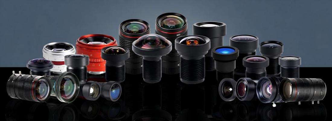
Various types of industrial lenses
5.Key considerations for selecting industrial lenses
When selecting a lens, we must first determine the client’s requirements:
1)Field of view, optical magnification, and desired working distance: When selecting a lens, we choose one with a field of view slightly larger than the object being inspected to facilitate motion control.
2)Depth of field requirements: For projects requiring specific depth of field, use the smallest possible aperture; when selecting a lens, opt for the lowest possible magnification allowed by the project constraints. For demanding applications, prioritize high-end lenses that offer superior depth of field.
3)Sensor size and camera interface: For example, a 2/3″ lens supports a maximum industrial camera sensor size of 2/3″; it cannot support industrial cameras with sensors larger than 1 inch.
4)Pay attention to the coordination with the light source and select a suitable lens.
5)Installation space: When the design plan is already determined, it is unrealistic to ask the client to change the equipment dimensions.
Post time: Oct-23-2026


