
1.What is lens image height?
Image height refers to the distance from the center of the image (the center of the optical axis) to the edge of the effective image on the optical lens‘s image plane; it is typically measured in millimeters (mm).
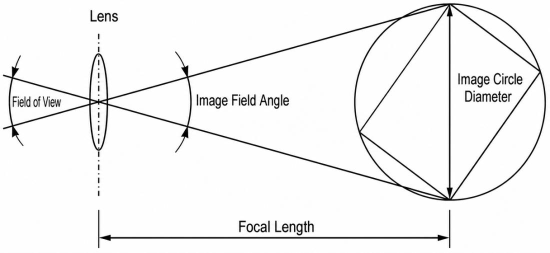
What is lens image height
The circular area that a lens can cover when it images an object onto a photosensitive plane (such as an image sensor).
You can imagine:
The lens is a “projector” that projects images onto the sensor.
The range of this projection is a “circle”—this is the image circle.
If the sensor size is larger than the imaging circle, the edges will be dark (dark corners).
If the sensor size is less than or equal to the imaging circle, the image can completely cover the area.
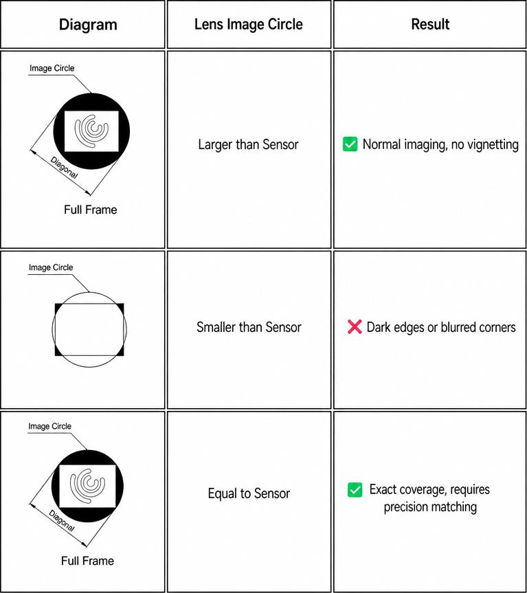
Lens imaging diagram
2.What are the imaging modes and how are they calculated?
Full-frame mode: chip length < image height, chip height < image height, chip diagonal < image height (Figure 5).
Vignetting mode: chip length < image height, chip height < image height, chip diagonal > image height (Figure 4).
Horizontal inscribed circle mode: Chip length ≥ image height, chip height < image height, chip diagonal > image height (Figures 2 and 3).
Vertical inscribed circle mode: chip length > image height, chip height > image height, chip diagonal > image height (Figure 1).
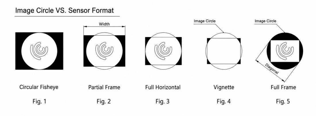
Schematic diagram of imaging modes
3.How can I find the corresponding distortion value using the image height and distortion table?
The following is a standard table showing distortion versus corresponding image height.
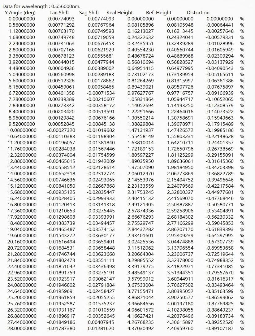
Let us take the AR0830 (3840×2160, 1.4μm) chip as an example:
Calculate horizontal field-of-view distortion using the table:
1)Calculate horizontal length: 3840 × 1.4 = 5376 (μm)
2)Convert to mm: 5376 (μm) / 1000 = 5.376 (mm)
3)Converted to semi-image height: 5.376 mm / 2 = 2.688 mm
4)Check the “Real Height” column in the table and find the value closest to 2.688: 2.688 → 2.68184302
5)Locate the Distortion column corresponding to the value closest to the target: 2.68184302 → -0.56230332%
Calculate the vertical field-of-view distortion using the table:
1)Calculate the vertical length: 2160 × 1.4 = 3024 (μm)
2)Convert to mm: 3024 (μm) / 1000 = 3.024 (mm)
3)Convert to semi-image height: 3.024 mm / 2 = 1.512 mm
4)Query the “Real Height” column of the table and find the closest value: 1.512 → 1.55803231
5)Find the distortion column corresponding to the closest value: 1.55803231 → -0.22148628%
Calculate diagonal field-of-view distortion using the table:
1)The diagonal length is calculated to be 6,168μm using the Pythagorean theorem
2)Convert to mm: 6168 (μm) / 1000 = 6.168 (mm)
3)Converted to semi-image height: 6.168 mm / 2 = 3.084 mm
4)Check the “Real Height” column in the table and find the value closest to 3.084: 3.084 → 3.11512062
5)Find the distortion column corresponding to the closest value: 3.11512062 → -0.69953658%
4.How can I calculate the field of view by looking up a table?
This is a standard table of angles and their corresponding half-image heights.
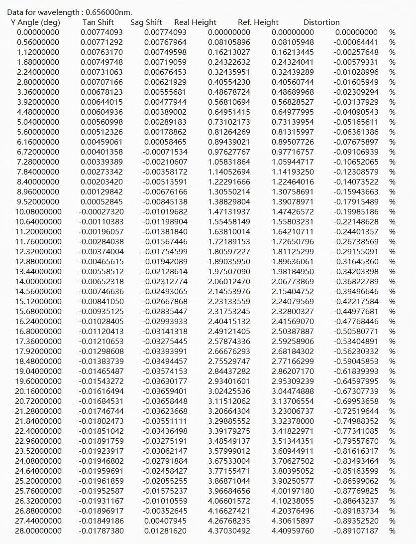
Let us take the AR0830 (3840×2160, 1.4μm) chip as an example:
Calculate the horizontal field of view using the lookup table:
1)Calculate horizontal length: 3840 × 1.4 = 5376 (μm)
2)Convert to mm: 5376 (μm) / 1000 = 5.376 (mm)
3)Converted to semi-image height: 5.376 mm / 2 = 2.688 mm
4)Check the “Real Height” column in the table and find the value closest to 2.688: 2.688 → 2.68184302
5)Locate the angle corresponding to the value closest to [Y Angle (Deg)]: 2.68184302 → 17.92°
6)Convert to full-field-height mode: 17.92° × 2 = 35.84°
Calculate the vertical field of view using the lookup table:
1)Calculate the vertical length: 2160 × 1.4 = 3024 (μm)
2)Convert to mm: 3024 (μm) / 1000 = 3.024 (mm)
3)Convert to semi-image height: 3.024 mm / 2 = 1.512 mm
4)Check the “Real Height” column of the table and find the closest value: 1.512 → 1.55803231
5)Locate the angle corresponding to the value closest to [Y Angle (Deg)]: 1.55803231 → 10.64°
6)Convert to full-field-height mode: 10.64° × 2 = 21.28°
Calculate the diagonal field of view using the lookup table:
1)The diagonal length is calculated to be 6,168μm using the Pythagorean theorem
2)Convert to mm: 6168 (μm) / 1000 = 6.168 (mm)
3)Converted to semi-image height: 6.168 mm / 2 = 3.084 mm
4)Check the “Real Height” column in the table and find the value closest to 3.084: 3.084 → 3.11512062
5)Locate the angle corresponding to the value closest to the [Y Angle(Deg)] column: 3.11512062 → 20.72°
6)Convert to full-image height mode: 20.72° × 2 = 41.44°
Post time: Nov-13-2026


