
In industrial vision systems, scanning lenses are critical optical components that enable high-precision, high-speed, large field of view measurements. Achieving such precision is a systems-level challenge that requires the coordinated integration of high-performance optical hardware, meticulous system calibration, and advanced image-processing algorithms.
I. Optical hardware: ensuring imaging accuracy from the source
The high precision of a scanning lens first depends on its optical design; the selection of lenses and other optical components determines the upper limit of the raw image quality that the system can capture.
1. Telecentric lens
Telecentric lenses are key to eliminating perspective distortion and are the preferred choice for precision measurement. Through a unique optical design, they ensure that image magnification remains constant over a specified range of object distances. This fundamentally eliminates the “near-large, far-small” perspective error caused by slight changes in object position with conventional lenses, thereby guaranteeing the stability of measurement results.
Moreover, their low distortion characteristics—high quality telecentric lenses typically exhibit distortion rates below 0.1%—further ensure the accuracy and reliability of measurement data.
It should be noted that the variable aperture of a telecentric lens should not be set too small; an excessively small aperture can induce diffraction, leading to reduced resolution and even edge-light attenuation (vignetting), which in turn degrades dimensional measurement accuracy.
2. Line-scan lens
Line-scan lenses ensure high-speed, large-format scanning and are primarily used to inspect continuously moving objects or large-area workpieces, such as thin films, steel plates, and printed materials.
Paired with line scan cameras, they capture images by scanning one line at a time through the relative motion between the camera and the object. These lenses offer high resolution; top-tier models can achieve resolutions down to 1 μm and support ultra-high-resolution line-scan sensors.
Moreover, to accommodate wide-width substrates, line scan lenses typically feature image circles of φ45 mm or even larger (e.g., φ90 mm-class systems), while sophisticated optical designs ensure sharp imaging across the entire field of view with minimal distortion.
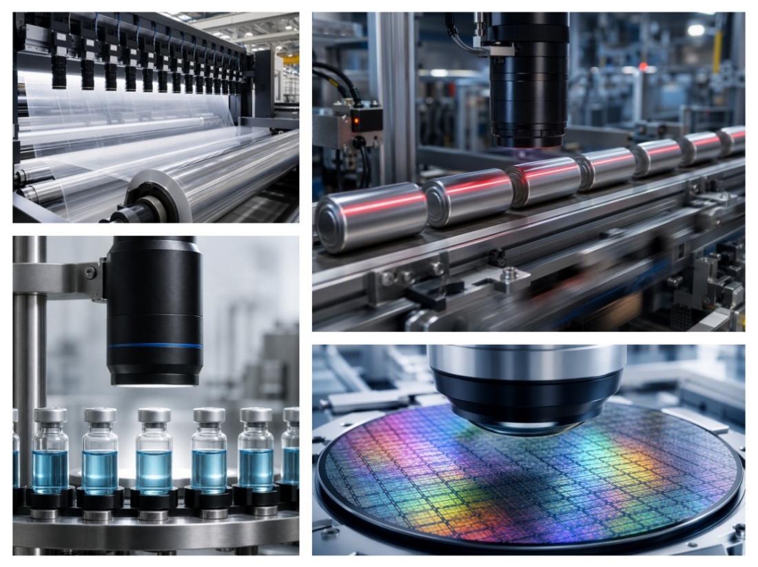
Line scan lenses are mainly used to detect continuously moving objects or large-format workpieces
3. Light source selection and lighting design
Using a line light source and coaxial telecentric illumination ensures sharp contour edges and steep gray-level transitions; uneven illumination can cause edge-extraction bias, introducing spurious measurement errors. For highly reflective workpieces, a polarized light source should be selected to suppress specular reflection interference. Different light sources directly affect edge contrast and the signal-to-noise ratio, thereby influencing the accuracy of subpixel edge extraction.
It should be noted that, when selecting a lens, its resolution must match the camera’s pixel size. Additionally, pay attention to distortion (precision measurements typically require less than 0.1%), depth of field (to ensure that workpieces with height differences remain in sharp focus across their entire surface), and the MTF curve (a comprehensive metric for evaluating the lens’s ability to reproduce fine details).
However, even with superior optical hardware, if the scanning mechanism is poorly designed or the system has not been precisely calibrated, measurement accuracy will still be severely compromised.
II. Imaging and synchronization mechanisms of typical scanning systems
In addition to 2D scanning based on line scan cameras, industrial vision employs a variety of 3D scanning technologies, all of which likewise rely on scanning lenses to establish precise optical mapping relationships.
1. Line-scan lens system
After understanding the optical characteristics of line-scan lenses—such as their high resolution and large image sensor format—the implementation of their scanning mechanism likewise determines the final accuracy. When used in conjunction with a linear-array CCD or CMOS sensor, a line-scan lens delivers exceptionally high spatial resolution and very low distortion along the scan direction.
During operation, the object under inspection moves at a constant speed on a motion stage, while the linear-array camera acquires images line by line and stitches them together to produce a complete, high-resolution two-dimensional image.
Synchronized scan control is critical to achieving this precision—the camera’s acquisition rate must be precisely matched to the object’s travel speed. It must match the scale exactly; otherwise, the image will be stretched or compressed, leading to measurement errors.
2. Structured light scanning system
The structured-light scanning system projects an encoded light pattern—such as sinusoidal fringes or Gray codes—using a DLP projector, while a high-resolution camera captures surface deformations. A phase-unwrapping algorithm then computes depth values pixel by pixel.
For example, in automotive panel inspection, it can achieve a repeatability of 0.03 mm, with a point-cloud density exceeding 500 points per square centimeter.
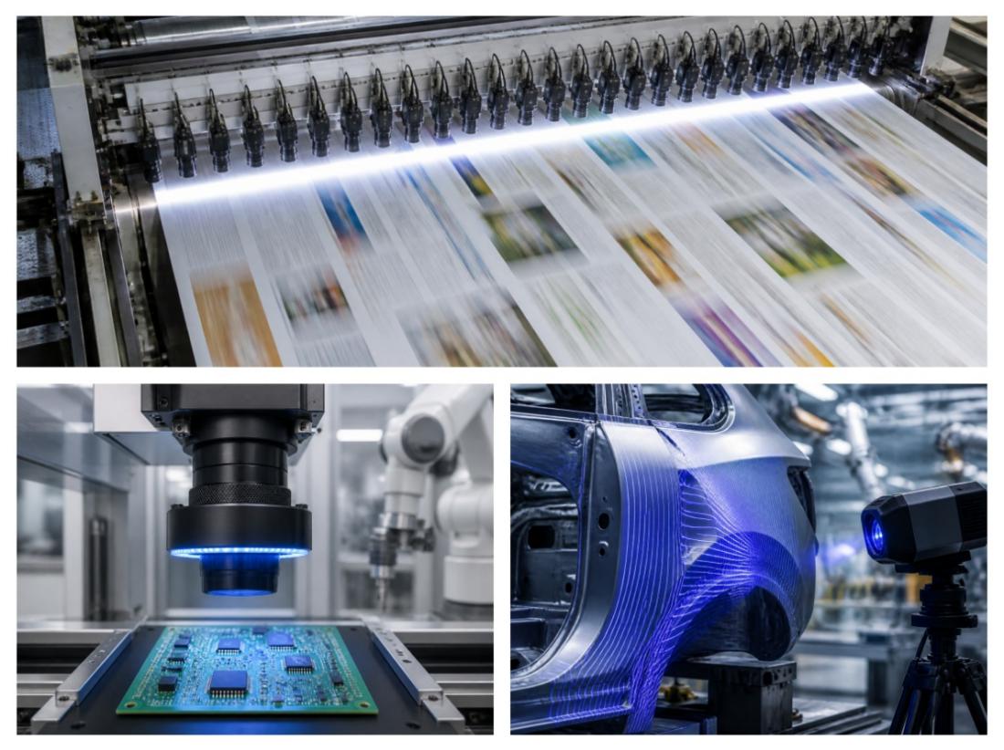
Structured light scanning systems are one of the typical scanning systems
3. Laser triangulation scanning system
The transmitter, receiver, and the measured surface form a triangular relationship with a fixed angle. When the laser line illuminates a curved surface, it undergoes positional displacement, and the sensor computes the three-dimensional coordinates in real time based on the change in the centroid of the light spot.
Taking a typical device from a certain brand as an example, at a working distance of 100 mm, it can achieve a single-point accuracy of 0.02 mm, with a scanning rate consistently maintained at 200 lines per second, making it well suited for reconstructing the contours of minute features such as turbine blades and gear tooth profiles.
In these systems, the scanning lens is responsible for establishing a precise, stable, and low-distortion optical mapping relationship between the sensor and the object under test.
III. System calibration and adjustment
Even when lenses leave the factory with low distortion, residual errors can still arise due to assembly and temperature variations. Calibration is an indispensable step in high-precision measurement, one that cannot be replaced.
1.Pixel equivalent calibration: Using a high-precision standard scale or a line-array-specific calibration target, establish the mapping between image pixel coordinates and world physical coordinates, thereby determining the true physical dimensions in the X (lens-horizontal) and Y (scanning-motion direction) directions.
2.Distortion calibration and correction: Determine the coefficients for radial and tangential lens distortion, then use software to perform geometric correction on the image, thereby correcting residual lens distortion and nonlinear deformation caused by mounting tilt.
3.3D coordinate mapping: By using images of a multi-pose calibration board, an accurate 3D mapping from image coordinates to world coordinates is established, correcting complex distortions and enabling direct measurements in the world coordinate system.
4.Flat-field correction: Eliminates brightness non-uniformity caused by the lens and light source, and equalizes the gray-scale response across the entire field of view.
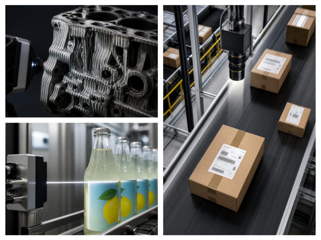
System calibration is an irreplaceable part of high-precision measurement
IV. Algorithmic applications from images to precise dimensions
The raw pixel-level images captured by the scanning lens must undergo a series of algorithmic processing steps to be converted into high-precision measurement results:
1.Sub-pixel edge extraction: By employing an appropriate algorithm, the true contour edges of a part are precisely localized between two pixels, thereby minimizing the impact of variations in light source intensity; this typically achieves an accuracy of 1/10 to 1/20 of a pixel.
2.Image preprocessing: edge-preserving filtering to remove noise without blurring the workpiece contours, and to eliminate spurious edges and false boundaries caused by reflections.
3.Geometric fitting: Perform straight-line, circle, and circular-arc fitting on contour points to suppress the influence of single-point noise, and output geometric parameters such as length, width, aperture, and spacing.
4.AI and deep learning: Modern measurement systems are increasingly integrating AI algorithms. Deep learning can be used to automatically identify measurement locations, intelligently match measurement routines, or assist in the precise localization of complex features and edge extraction, thereby further enhancing measurement stability and accuracy in challenging scenarios.
In summary, high-precision measurement using industrial vision scanning lenses requires a close integration of hardware, calibration, and algorithms to enable industrial vision systems to achieve stable and reliable measurements at the micrometer level or even higher precision on complex production lines.
Post time: Nov-10-2026


